Introduction :
I had always thought of ATV as something that would interest me, but knowing absolutely nothing about microwave bands and not being a dab-hand a 'home brew' I always knew it was nothing more than me thinking 'that's something I'd like to try... one day'.
Then many many years later I read a short article in the ATV column of the September 2017 edition of RadCom that stated 5.6GHz ATV could be achieved by using cheap 'First Person Video' (FPV) transmitter and receiver units – intended for use in drones - for less that £30.00.
As I would see, £30.00 may have been an underestimation the way I did it, but hey – the world of ATV was now within reach.
Having discussed it at our radio club, it was clear there were a few others interested in this and we set up a project with an aim of getting 2 or 3 completed stations set up and working. Nick, G0HIK, was first to get started and built up a station using a dish as the antenna, relay switching for RX and TX and a host of other features all built into one .
I opted for something slightly different, and that is what I shall describe here. Although my system would ultimately cost more (mainly due to 2 antennas as opposed to 1) it was a method more within my capabilities (relays and the like are not my forte) and it shows that ATV can be achieved without too much technical know-how. Plus is allows us to compare the differences in two slightly diffident station set ups, yet delivering essentially the same thing... 5.6GHz ATV.
My station comprises of the following :
- TX unit and camera
- RX unit and monitor (and speakers)
- 2 panel antennas
- 12v battery supply and power distribution
- Media card reader for test card / call sign display
- 5v supply
- Tripod
- Beacon unit
Each section is described in detail below...
TX unit and camera options
The RadCom article talked about First Person Video (FPV) transmit and receive units (used predominantly for drones), and these are the essence of the station. So the first thing I did was email the British Amateur TV Club (BATC) – who had written the article - for more information on the units required.
Upon receiving a speedy response, I ordered a couple of TX units from eBay – the units cost around £8.00 each and would be delivered from China. The order was placed (along with RX units, described further down) and they arrived in about 10 days – which was very quick indeed. These first set of units were actually used by Nick, G0HIK, for his system, so I ordered some more – these took over 2 months to arrive, so in the same time I placed an order for an addition 2 units from a UK seller, which costs slightly more, but arrived within a week.
The TX units in question are : TS58285.8GHz 600mW 32 Channels Mini Wireless 2dbm A/V Transmitter Video TX
They offer an output of just 600mw, but this combined with excellent gain on suitable antennas, can make signal acquisition over a distance of 80 miles. The units can be set to a certain frequency (channelised), and the recognised standard for 6cm ATV in the UK is 5665MHz so it was important to ensure this frequency is covered.
These units offer 32 channels covering bands A, B, E and F and have two switching buttons for the band and channel. Conveniently they feature power off memory for last channel and band saving, so once set you don't need to worry about setting the frequency again.
Specifications:
- Video format supported: PAL and NTSC
- Antenna connection: RP-SMA (Reverse Polarity SMA – more on that later)
- Power input: 7 – 24 Volts
- Transmitting power: 600mW
- Supplied antenna gain: 2dbm (the supplied antennas were not used, other to ensure the units worked)
- Working current: 310mA at 12V
- Video bandwidth: 8Mhz
- Audio bandwidth : 6.5Mhz
- Dimension: 23x 25x 7.7mm (excluding antenna)
Frequency range:
FR1 : 5865, 5845, 5825, 5805, 5785, 5765, 5745, 5725 MHz
FR2 : 5733, 5752, 5771, 5790, 5809, 5828, 5847, 5866 MHz
FR3 : 5707, 5685, 5665, 5645, 5885, 5905, 5925, 5945 MHz
FR4 : 5740, 5760, 5780, 5800, 5820, 5840, 5860, 5880 MHz
As mentioned above these units use RP SMA connectors – so an adaptor is required to connect to the panel antenna which has an N type female. A RP SMA Male to N Type Male adaptor was acquired for a few pounds, again from eBay.
The TX unit does get quite hot when transmitting, even for short periods, so a piece of head sink was glued to the back of the unit to help with heat distribution. As nearly all ATV activity takes place outside the cooler surroundings also helps with this. A 12v fan to cool the unit may be added if required.
The TX unit was mounted in a case which allows for direct connection to the panel antenna. The units come with a lead supplied for power, audio, video and ground, making for easy connection. RCA phono sockets were added to allow easy connection of video and audio sources (the ground was added to the video source). As there is no obvious way of knowing if the unit is powered up (there's no LED or anything to indicate if power is on), so a simple LED was added to show that power, and therefore TX, is on.
A power lead comes from the bottom of the case and is plugged into the 12v power distribution unit (described further down).
As RCA phono sockets were added, this allows for different AV devices to be used. For ease and initial testing 2 small 12v cameras were used. Any video camera with a composite source will work and these have also been used.
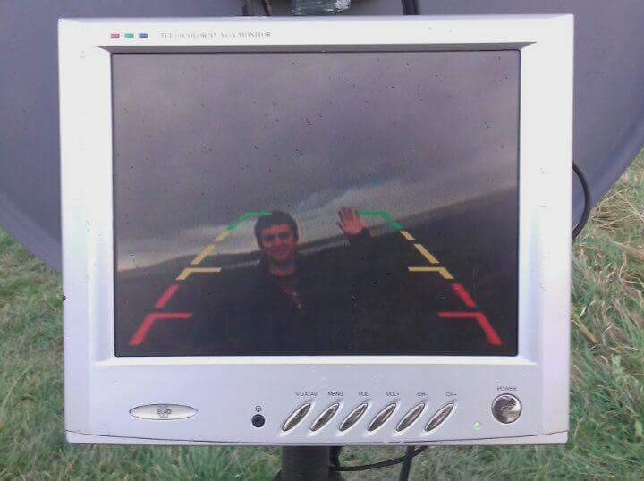
I already had a 12v car reversing camera in a drawer in the shack so that was used initially and worked well, giving clear video signals. There were a couple of downsides to this camera, one being that it was video only, so no sound was possible and the other was that as it was a 'reversing camera' intended for a car it had red, yellow and green 'marker lines' that were transmitted. Not the end of the world, and certainly fine for testing purposes.
An added bonus was that the camera was waterproof, so ideal for using during winter !
Options for a new 12v camera seemed to be limited, and it always seemed to be a 'compromise' when finding alternatives. Another camera which was used offering the added bonus of sound, but only a black and white video signal. But again, the low cost (about £5.00 a camera) from eBay made it a suitable choice when trying to keep the cost of 'sundries' down.
These little 380 line PAL black and white mini cameras were brand new and feature switching infra red and have sound. The infra red LED's automatically switch on when light levels get low. They have standard AV connectors for audio and video and require a 12v power supply – a must as I wanted to power all the kit from one 12v distribution unit. The main body of the camera is just 35mm x 25mm x 15mm and they are fitted with a 3.6mm lens.
What the black and white video looses, the audio quality from these cameras more than compensates for. As these ATV systems are FM, the audio is just like any other FM signal – loud and clear!
As already mentioned, I use separate antennas for transmit and receive. More details of the antennas is further down, but for TX a 5.8GHz 24dBi 'Gibeon' panel antenna is used – which covers down to 5665MHz with an SWR of 1:1.
I used slightly differed panel antennas for RX and TX simply due to supply issues, and being only able to purchase one of each type – unless I wanted to spend well over £100 per antenna. As it is the antennas came in at a little under £100 for the two – so slightly more than the 'Get on ATV for under £30.00' RadCom had promised!
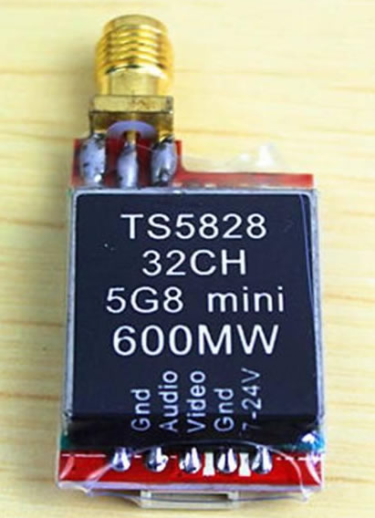
TS5828 5.8GHz 600mW 32 Channels Mini Wireless 2dbm A/V Transmitter
5.8GHz 600mW A/V Transmitter unit
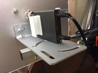
5.8GHz 600mW A/V Transmitter unit installed in case with A/V phono sockets and 12v input lead
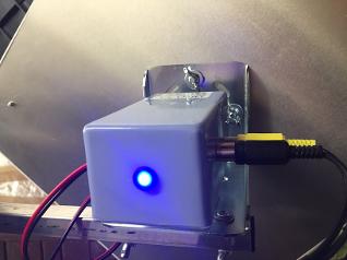
A/V Transmitter unit attached to panel antenna - LED was added to show power/TX is on
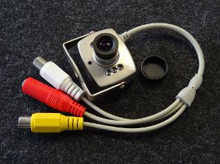
12v camera
RX unit and monitor
Similar to the TX units, the RX units were ordered via eBay at a cost of around £10 each and were delivered from China within 10 days (the second batch again taking over 2 months)
The units in question are 32CH 5.8GHz Video/Audio FPV RC832 Wireless Receiver, again intended for FPV drone usage.
Specifications:
- Video format supported : PAL / NTSC
- Antenna connection: RP-SMA
- Power input: 12V
- Working current: 200mA max
- Antenna impedance: 50Ω
- Supplied antenna gain: 2db
- RX sensitivity -90dBm
- Video impedance: 75Ω
- Dimension: 80x 65 x15mm
- Weight: 85g
Frequency range:
FR1 5865, 5845, 5825, 5805, 5785, 5765, 5745, 5725 MHz
FR2 5733, 5752, 5771, 5790, 5809, 5828, 5847, 5866 MHz
FR3 5707, 5685, 5665, 5645, 5885, 5905, 5925, 5945 MHz
FR4 5740, 5760, 5780, 5800, 5820, 5840, 5860, 5880 MHz
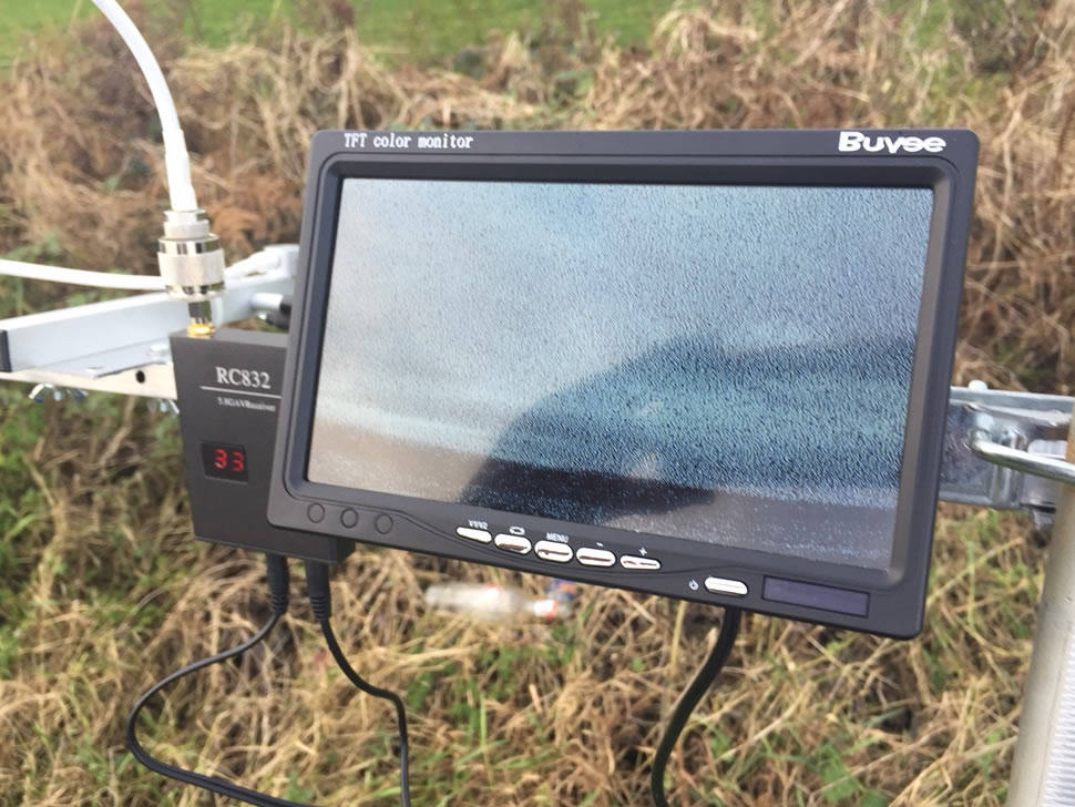
There was very little to do with these units, set to channel 33 (which sets the receiver to 5665MHz) and use a reverse polarity SMA Male to N Type Male adapter to allow it to be connected directly to the antenna.
The antenna for the RX station is a TL-ANT5823B 5GHz 23dBi outdoor panel antenna, which will be described in more detail further down.
Power is supplied from the 12v distribution unit and the video signal is fed into a 12v monitor, with the audio being fed into a set of portable speakers.
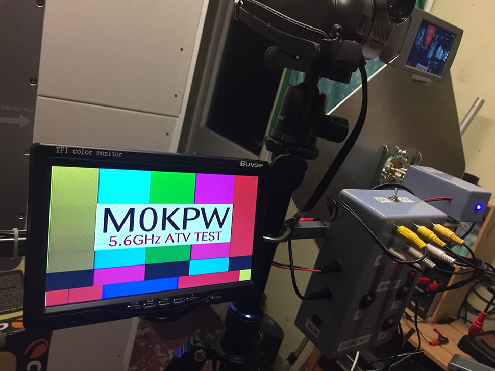
The monitor is something else I had in the shack, it's a 7 inch monitor intended for use in a car for viewing a reversing camera. Works with both PAL and NTSC it have 2 video inputs, but the downside is no audio – hence the use of portable speakers. There are adjustment for brightness, colour and contrast plus format settings for 4:3 or 16:9 sources.
It's very light weight so helps keep the overall weight of the station down, and it was easy to attached to the tripod arm with a couple of bolts and wing nuts.
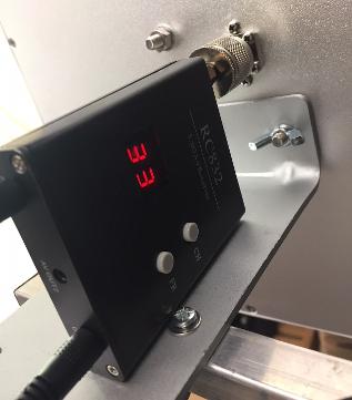
RC832 Wireless Receiver unit
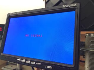
7 inch monitor - 12v
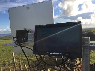
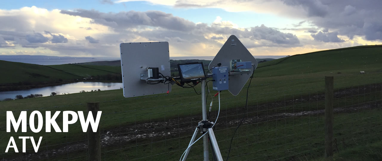
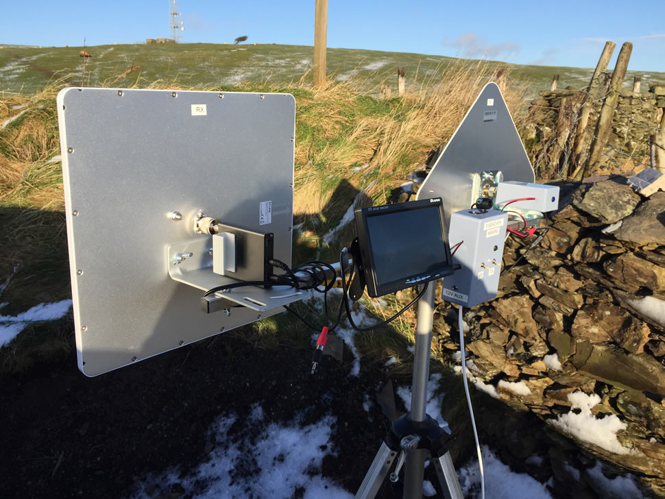
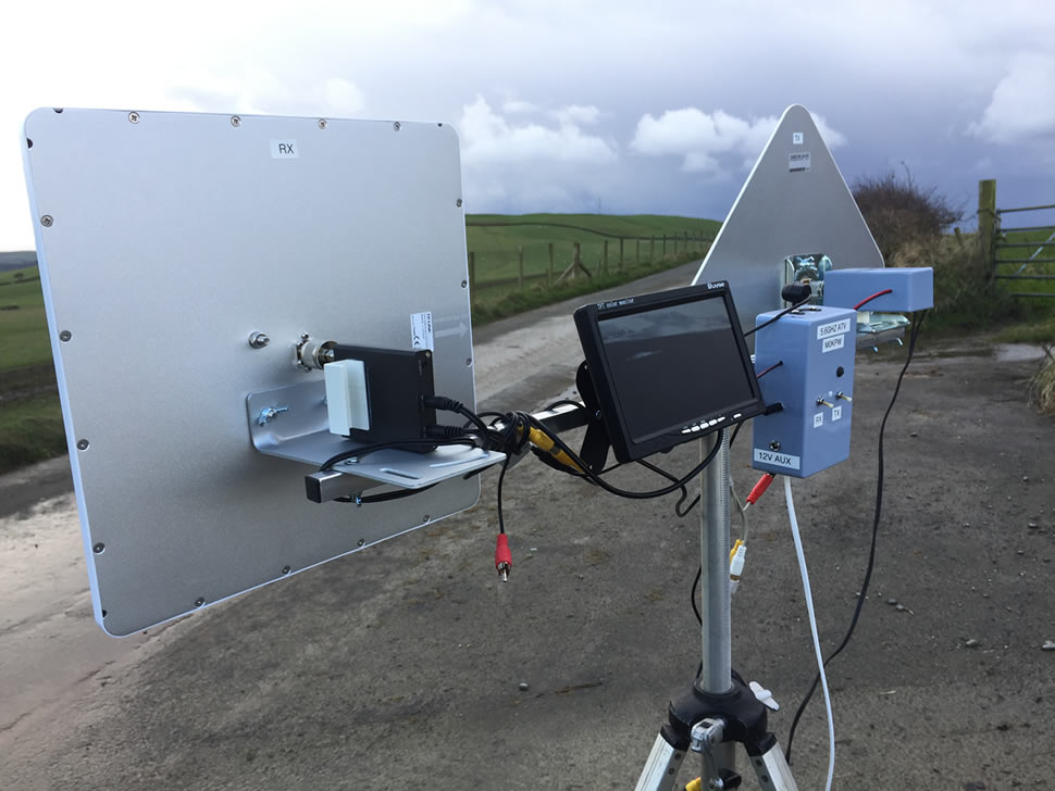
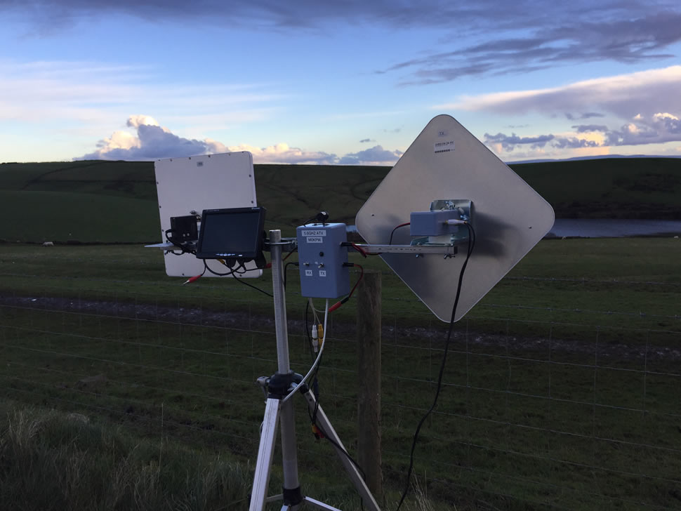
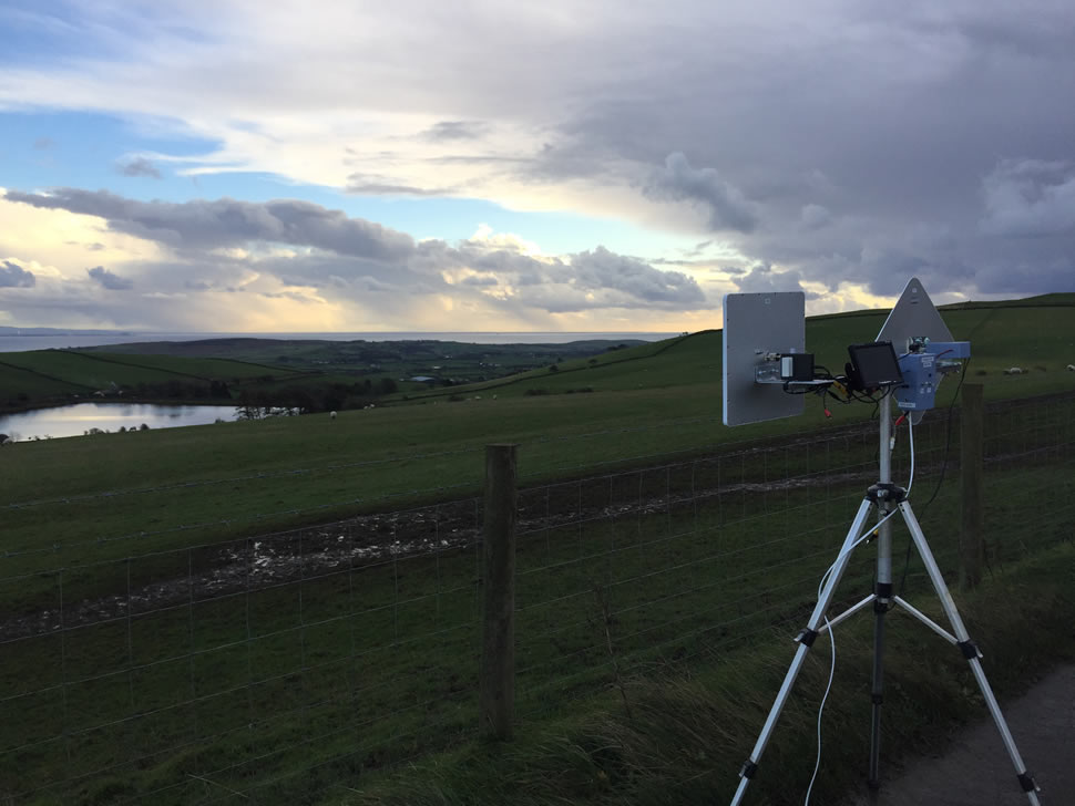
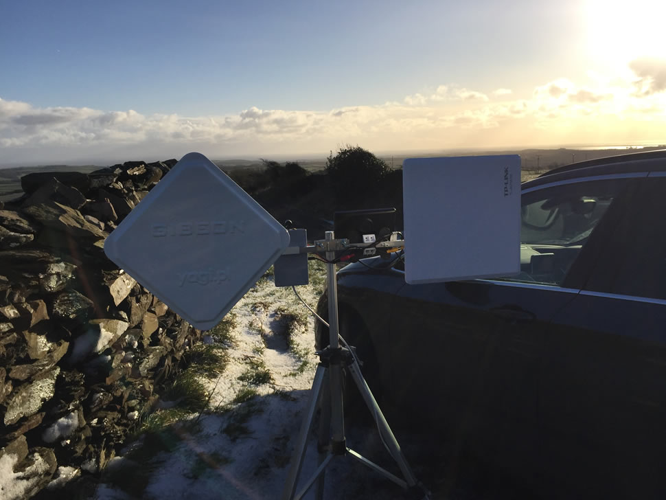
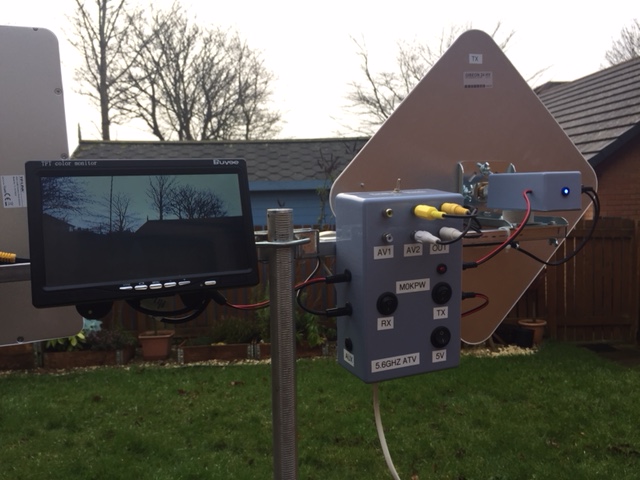
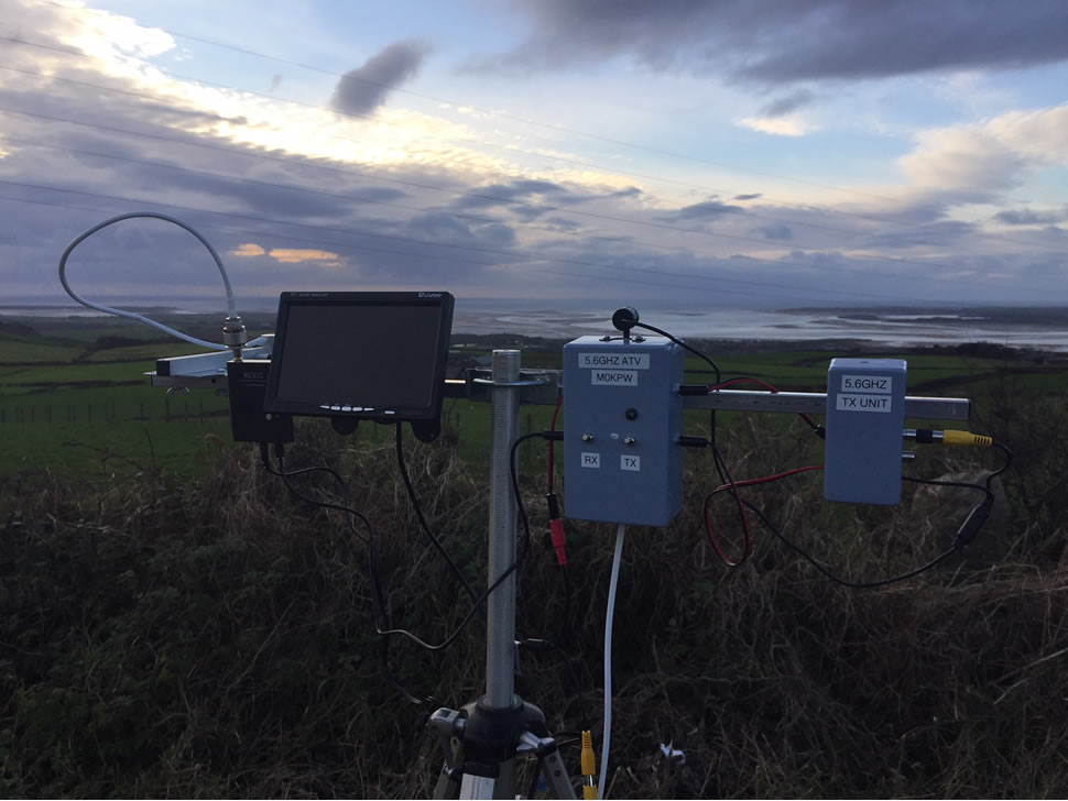
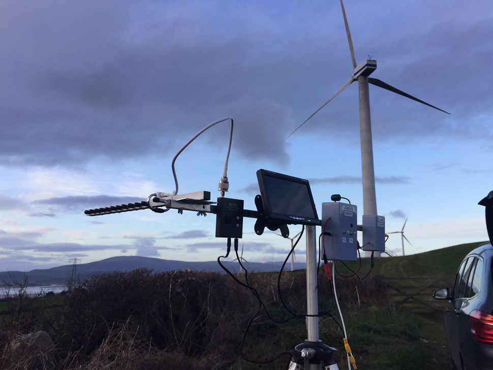
Out in the field /P
Antennas
As mentioned I use separate antennas for RX and TX, thus removing the need for changeover relays. This does of course make for a more expensive system, but a sacrifice I was happy with.
Initially my plan was to try a panel antenna on TX and a yagi for RX. I had seen a 16dBi 5.8GHz yagi that covered the frequency in question, so thought I'd give it a go. Following some initial tests with Nick, G0HIK, it did not seem to perform very well, so the yagi was removed and swapped for a panel antenna instead – this vastly improved the system.
I use two slightly different panel antennas, as mentioned, more than anything to do with availability at time of purchase.
The TX antenna is a '5Ghz 24dBi HV WIFI RP-SMA Wireless Signal Booster' antenna obviously intended for WiFi use, but works perfectly for ATV. At a cost of £44 delivered, its pricey, but a price I felt worth paying. It has a female N type connector on the back so the TX unit can be connected straight to it with no need for any coax that would start to introduce losses. The antenna is easy to mount with bracket that is attached to the back of the antenna, either horizontally or vernally, which will also determine the polarisation of the antenna. Even though this is an FM system, the antennas are horizontally polarised for ATV.
Specification :
- Gain : 24dBi
- Polarization : Horizontal or vertical
- Horizontal half power beam-width : 10.5°
- Vertical half power beam-width : 10.5°
- Connector : Female n type
- SWR : 1:2 (when intended for WiFi use)
- Impedance : 50 Ohm
- Dimensions : 330mm x 330mm x 20mm
- Weight : 1.3kg
The antennas are where the majority of the weight in system comes from, but again, a sacrifice I am happy with – and it does not make the system exceptionally heavy.
Having 2 panel antennas means you need to be mindful of any wind resistance – or lack if it, if the wind is not in a favourable direction. But there is little difference between these and say a satellite dish – both tend to act in the same way. So a weight on the tripod is advisable to prevent the system falling over in windy conditions.
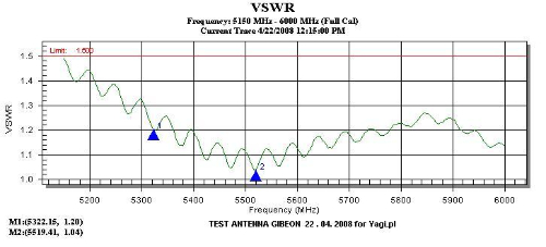
Allot of research was done to ensure this would be a suitable antenna for ATV needs and an SWR plot was received from the manufacturer which shows the SWR at 5665MHz would be around 1:1 so ideal for use at this frequency.
There was a problem with stock, so the UK stockist I bought this antenna from arranged for one to be sent to me direct from the manufacturer in Poland, and it took about a week to arrive.
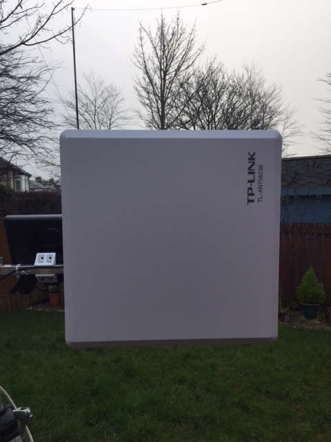
Due to the stock issue of the antenna above, the second, which is used for RX, is slightly different. Instead a TP Link TL-ANT5823B antenna was bought from Amazon at a cost of £55.00 (it was on offer at the time as these are currently retailing at over £80)
The TL-ANT5823B covers 5GHz and offers a gain of 23 dBi and is again intended for WiFi use but works perfectly for 6cm ATV.
Specification:
- Gain : 23dBi
- Connector : Female n type
- Weight : 1.36 Kg
- Frequency : 5.15 to 5.85GHz
- Impedance : 50 Ohms
- VSWR(MAX.) : ≤1.5
- Polarization : Vertical or Horizontal
- Maximum Input Power 100W
- Dimension : 320×320×20(mm)
Again, this antenna is a key contributor to the weight of the station. It is easily attached to the tripod boom by means of a bracket that is attached to the antenna (which determines the polarity) and the RX unit connects directly to the antenna via an N type / RP SMA connector.
Ensuring this would have a low SWR on 5665HMz, I first checked with the manufacturer before purchase. As per the other panel antenna the SWR is around 1:1 on the required frequency.
Radiation patterns are shown below :
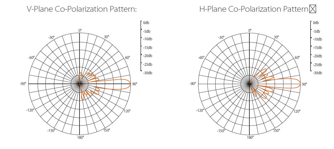
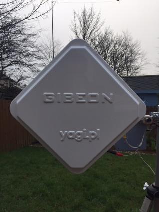
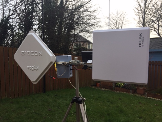
5Ghz 24dBi HV WIFI RP-SMA Wireless Signal Booster antenna by 'Gibeon'
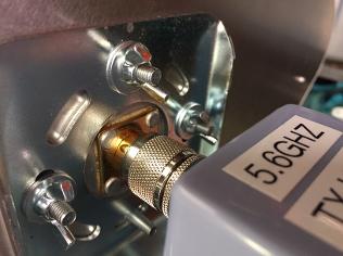
Connecting the TX unit to the antenna
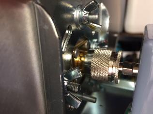
N type to RP SMA connector
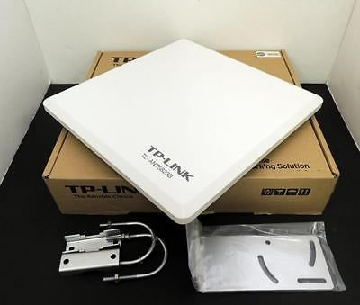
TP Link TL-ANT5823B antenna
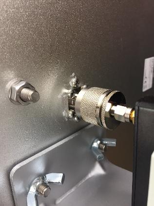
RX unit connected to the antenna
Fitting the antenna bracket to the boom for horizontal polarisation
12v Distribution Unit
TX unit and camera, RX unit and monitor all require power (conveniently 12v for all) so I decided to build a 12v distribution unit. Nothing fancy, just 12v in (with a fuse – just in case!) with multiple 12v out to supply all units.
A plastic project case from Maplin measuring 114.5mm x 184.5mm x 62.5mm was perfect for the job. And it would also allow room for some AV switching sockets and a 12v to 5v converter (which is used to power the 5v media card reader for displaying a test card)
Power is supplied from a lead from a 12v 26Ah battery which is connected to piece of choc block / terminal blocks. This is then fed to multiple 2.1mm DC sockets. 2 sockets are required for the RX side of things (RX unit and monitor) and 2 sockets are required for the TX side (TX unit and camera), both have switches which effectively switch on the RX or TX as required. An additional 2.1mm socket – not controlled by a switch - is added for an aux 12v supply should it be needed.
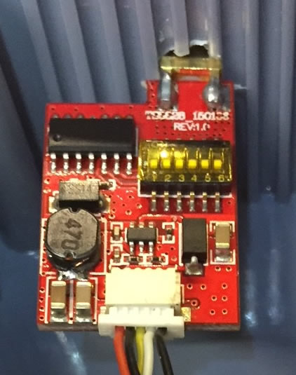
On the TX side of the case a 3 amp 12v DC to 5v DC Converter Regulator is added, which is switched, and is used to power the media card reader (more on that below)
Specification :
- Input voltage: 12V(22V MAX)
- Output voltage: 5V
- Output current: 3A(MAX)
- Max power consumption: 15W
- Converter Size: 6.50 x 2.70 x 1.40cm
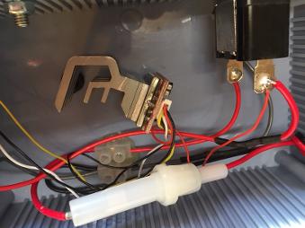
Construction on the 12v distribution unit is very straight forwarded, and no major expertise is needed – just basic soldering and drilling of a few holes in the plastic project case. An LED is added to the TX switch so the users knows the system is in transmit, and it's also a good indicator that the unit is receiving power.
A 5 amp fuse it added to the main 12v in supply in case of any problems. Although not difficult, the distribution unit was the most time consuming aspect of the project and went through 2 variations – with a more basic one created to start with, before building an 'improved version 2' which featured the 5v regulator (previously it was just an extra lead to carry around) and the addition of the AV switch which cut down on the need to swap leads over during a contact.
As all the various aspects all draw a low current, a 26Ah battery is plenty to run the station for a lengthy period of time.
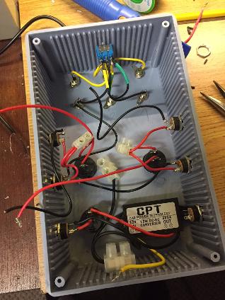
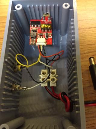
Work in progress - the only real work involved in setting up the station.
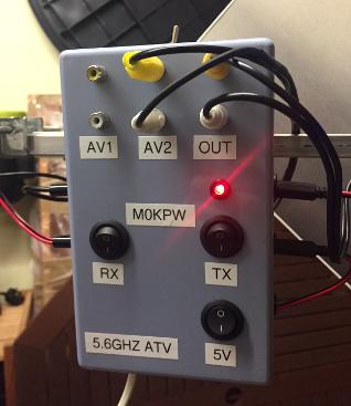
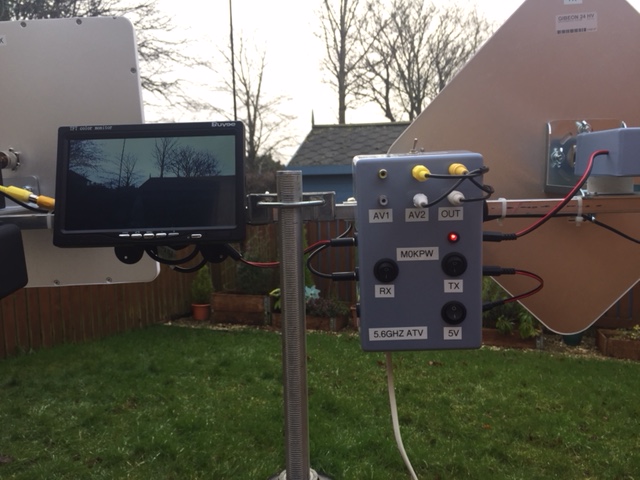
Completed distribution unit
Test Card and displaying of call sign
A test card was created as a JPG file and a way of feeding this JPG file into the transmitter is needed. There are various options including using a Raspberry Pi, but I opted for the easiest way by using a Media Card Reader which I had in a drawer doing nothing.
The reader in question is a 'Sandisk Photo Album & 8 in 1 Card Reader With Remote SDV2-C-E30' and takes media cards of various formats (SD, smart media, XD picture card etc) and also has a USB port.
Importantly there is an AV / composite output which can be fed into the TX unit allowing for the transmission of the JPG file.
And as a way of complying with licence conditions, a call sign caption JPG file was created that can be transmitted at least every 15 minutes.
The Media Card Reader requires 5v and is powered by the 5v supply from the power distribution unit. As the TX unit requires 2 AV inputs (one for camera and one for Media Card Reader) an AV switch was built into the power distribution unit so that the video (and audio if required) sources can be switched in easily.
A simple on - off - on switch swaps the source from camera to test card / call sign as required.
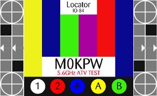
M0KPW ATV Test card jpg
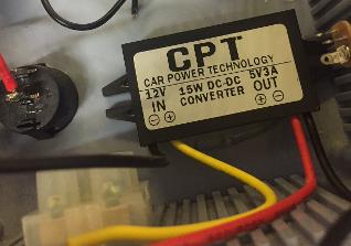
12v to 5v DC converter
Fitting the station together
A club member donated a suitable tripod. It's a pretty standard tripod, the 3 legs can be adjusted easily in height and there is an adjustable centre column giving a bit of extra height (the maximum height I can achieve with this tripod is 144cm). The camera mount came away from the tripod with very little encouragement with made it easier to attached a horizontal cross section which would hold all the elements that form the station. The cross section is a boom from an old HB9CV 4m antenna, with a length of 80cm and 1.6cm x 1.6cm square. It is attached to the tripod with its antenna bracket using wing nuts so it can be removed by hand if needed. Holes were drilled for attaching the antennas and monitor – but that was the sum total of 'metal work' required.
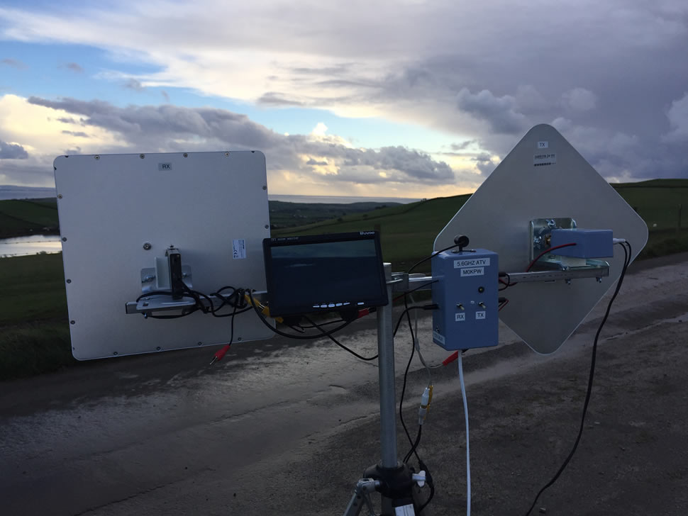
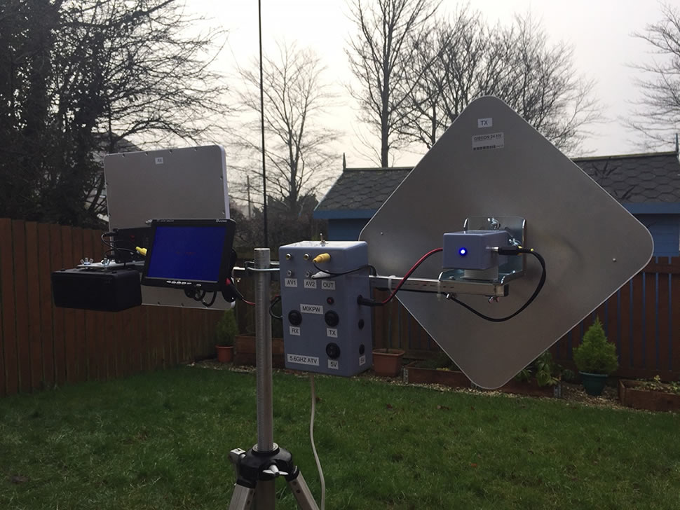
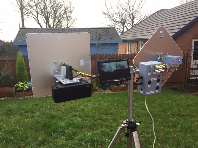
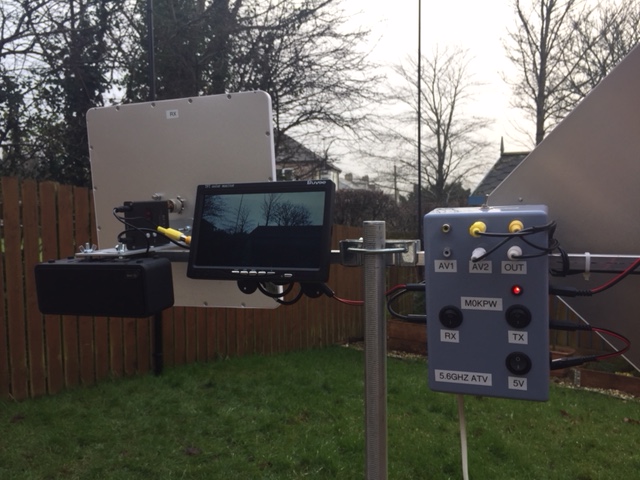
I decided on having the RX side of the station of the left, with the TX on the right – with the 12v distribution unit in the middle.
The RX antenna is bolted (horizontally polarised) to the boom with it's supplied right angle bracket using wing nuts – it fits very securely to the boom. The RX unit is connected directly to the RX antenna using an N type to RP SMA connector, next is the 7 inch monitor. This has a stand which has been bolted to the boom (some plastic corner blocks have been added to the boom to give extra support) – the angle of the monitor can be adjusted, plus it can be taken off the bracket easily should the need arise. As the monitor does not feature sound, a small set of amplifier speakers are added when needed. The audio out from the RX unit is simply fed into the speakers input socket.
In the middle (to the right of the mast clamp) is the 12v distribution unit. This is attached by gluing a piece of 16mm white plastic coupling (intended for use with 16mm by 16mm MK conduit trunking) to the back of the unit to act like a clip. This allows for the easy removal of the unit and is quite sturdy.
Next is the TX antenna - again attached horizontally with the supplied bracket and wing nuts - with the TX unit connected directly to it, again with an N type to RP SMA connector.
One of the 12v black and white cameras is attached to a piece of 16mm white plastic coupling and can be attached to any part of the boom.
The Media Card Reader has a 25mm white plastic coupling glued to the back, and this is clipped to one of the tripods legs to keep it securely out the way.
Power leads for all the units are just connected to the relevant socket on the distribution unit, whilst AV leads are run from the RX unit to the monitor for the receive side of the station, and from the camera and media card reader (via the AV switch) to the TX unit for transmission.
It may not be the most lightweight system in the world, but it is for from being unmanageable and it all folds down to fit into the car with out having to dismantle everything (I just remove the 12v distribution unit and camera)
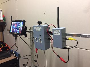
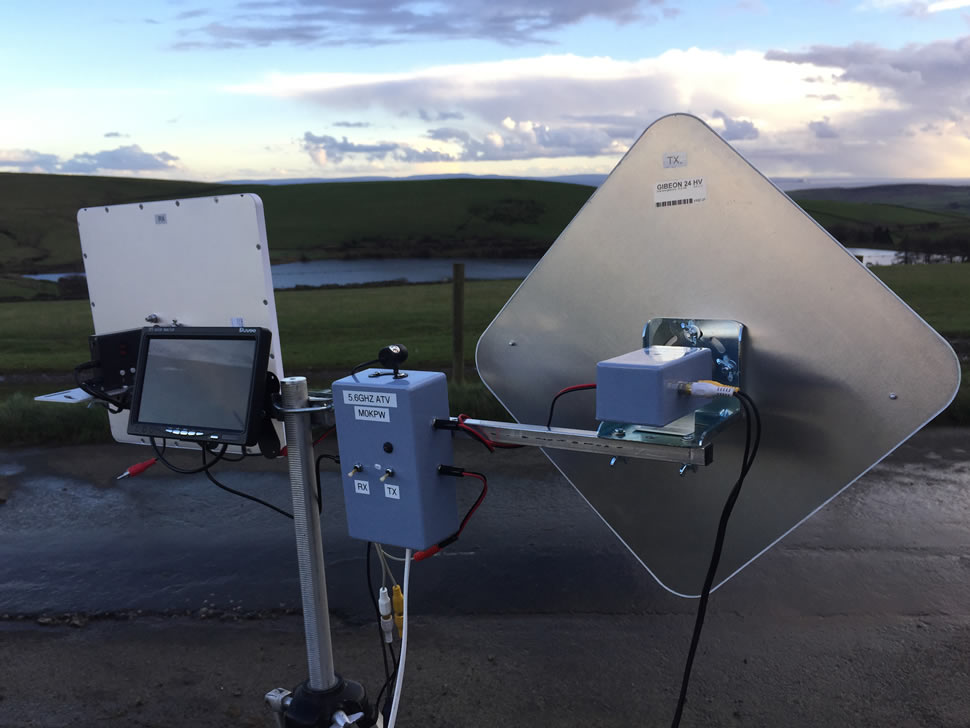
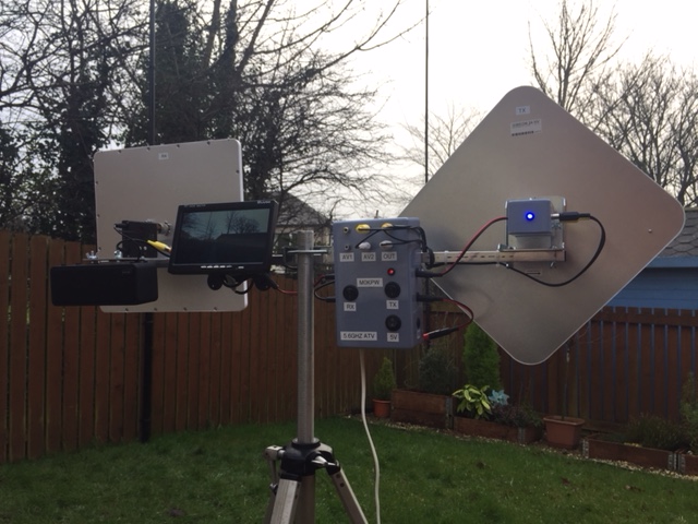
Tripod and boom, with the units set up for initial testing
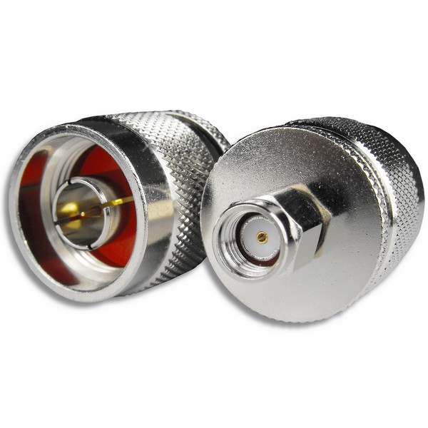
N type to RP SMA connectors
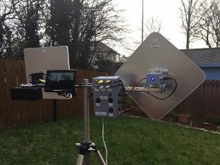
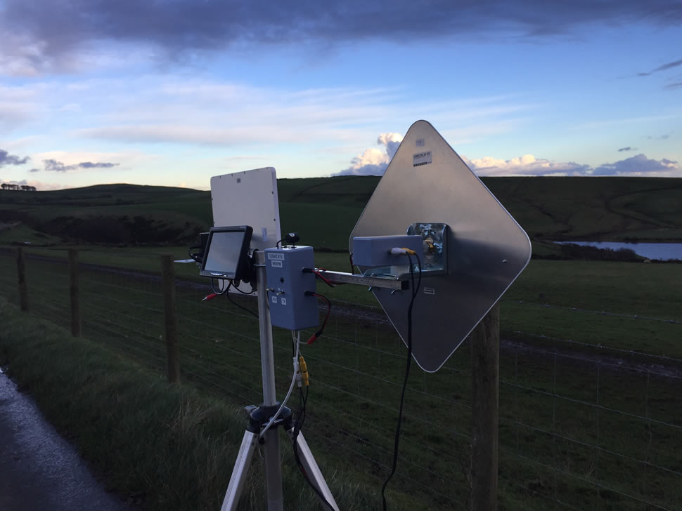
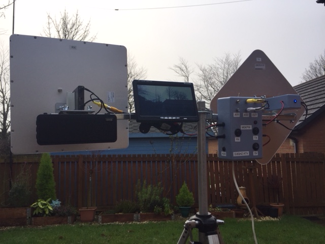
Completed station
Gallery of completed station
TX beacon for testing
For testing purposes a TX beacon was built that could be used for testing the RX station, proving alignment and a host of other things.
The beacon is simply a TX unit (5.8GHz 600mW 32 Channels Mini Wireless 2dbm A/V Transmitter Video TX), again with heat sink glues to the back to help dissipate some heat.
Housed in a plastic project box, with an on/off switch (with LED to show power / TX is on) and fed from an 12v battery source. I use a smaller 7ah battery as there's very little consumption from the devices and the 7ah battery is physically smaller.
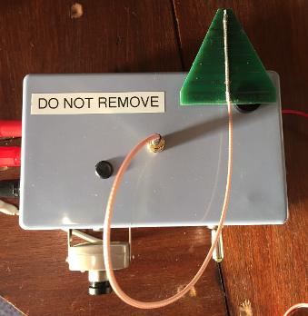
Antenna wise, I use a log periodic printed circuit board antenna (WA5VLB 2 – 11 G LPY).
This is the same antenna that Nick, G0HIK, uses on his dish ATV system. However I don't use a dish as with it only being a beacon it is not needed to transmit over particularly long distances – although it works at a distance of 10 miles and probably much further.
These log periodic printed circuit board antennas cover 2100 to 11000 MHz and are a perfect fit for 5.6GHz ATV, and cost around £5.00. A small length of microwave coax needs to be soldered the full length of the antenna, which is a job for a steady hand!
AV phono sockets were added to allow a video and/or audio source. A 12v black and white camera was attached to the front of the beacon so a there is always a source, but any video/audio source can be used.
RIGHT : Top, constructing the beacon. Bottom, completed beacon with WA5VLB 2 – 11 G LPY
Linear Amplifier
As stated the TX power is only 600mw, but distances of up to 80 miles can be achieved with this power.
Once this has been achieved, or as long a distance that we can achieved, I have purchased a linear amplifier - '5.8Ghz FPV Transmitter RF Signal Amplifier' (again from eBay) to see what can be achieved with 2w.
Specification :
- Frequency Range : 5.8G (5600MHz~6000MHz)
- Dimension: 60mm x 27mm 22mm
- Power Supply: 6V – 23V CD
- Input Power: -3dBm to 27dBm
- RF Output Power: 33dBm (2W)
- Weight: 45g
Gain guide :
3dB-6dB @ 5.60GHz to 5.75GHz
5dB-8dB @ 5.75GHz to 5.85GHz
3dB-7dB @ 5.85GHz to 6.00GHz
As yet the station has not been run with the linear amplifier, but it will be during 2018 and it will be interesting to see what the results are like.
I hope you found this interesting and it shows that with some simple research and very little microwave know-how, the world of 5.6GHz ATV can be achieved. Due to the project being started in November 2017, the furthest distance achieved so far is just under 12 miles, but we know that much greater distances can be achieved and this will be worked on in early 2018. Hopefully up to the dizzy heights of 80 miles plus.
If you have a line of sight to south Cumbria (IO-84 - Barrow in Furness / Ulverston area) and you would like to arrange a sked for 5.6GHZ ATV please drop me an email at m0kpw@aol.com
Testing and operating
This is a line of sight station, so when planning tests and activations it's good to check for LOS between the 2 stations before starting. A tool that I use is https://www.solwise.co.uk/wireless-elevationtool.html which will give an indication of line of sight paths and highlight any areas where LOS will not work – allowing both stations to find suitable operating positions. It's proves to be very accurate, but just bear in mind it will not factor buildings, trees etc. into it's calculations, so be mindful of the terrain between your station and the one you're wanting to work.
With a relativity narrow beam-width, alignment is key so you need to have a bearing on the station you want to work. Shorter distances where you can see the area of the other station are relatively easy, simply have one station transmit and the receiving station can set up the antenna for best alignment – something that's relatively simply over a distance of 10 to 20 miles as you can set up pointing in the general direction (as long as you know your local geography).
More on testing and operating to follow shortly...
Gallery from early testing before station was completed
Audio test with M0TEB carried out on a windy day in December 2017
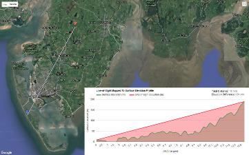
Distance and elevation plot